 |
|
|
|
Amplifier Settings
Adjusting the LEVEL control
Adjusting the XOVER control
|
|
A-40 Power Wire
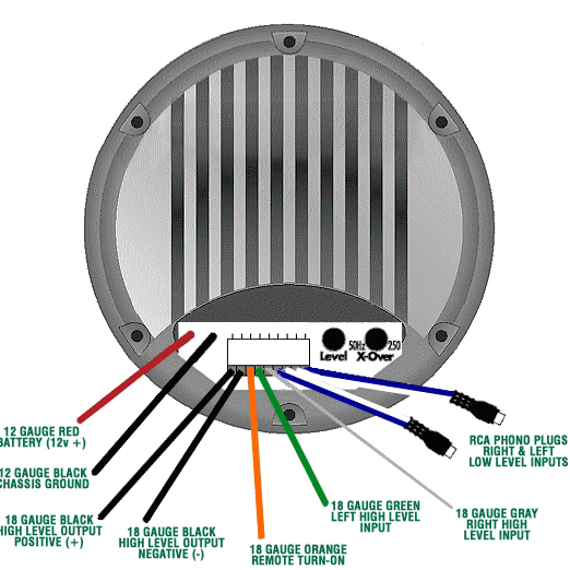
The 12 gauge red wire coming directly
out from the amplifier is the 12 Volt positive power wire. It must
be connected to the positive terminal of the battery to provide
a power source with a low voltage drop and low noise. Do not make
the power connection at the fuse block or any point other than the
battery. Improper power sources can reduce output and cause distortion.
The fuse holder should be connected to the battery's
positive terminal. The fuse is designed to prevent fire or damage
to your car, should the battery wire short to ground. Wait to insert
the fuse into its holder until all power connections have been made.
If it is necessary to lengthen the battery wire,
add the required length between the amplifier and the fuse holder,
not the fuse holder and the battery. Use 12 gauge or larger to extend
the battery wire. It is best to use as short a wire as possible.
Be sure you DO NOT run the power wire next to
the input cables of the amplifier, as this may induce noise.
Avoid running the power wire near the radio's
antenna or power leads, or near sensitive equipment or harness.
The power wire carries substantial currents and could induce noise.
top
|
CAUTION: DO NOT substitute the 15 amp fuse included
with the Amplified Bazooka with anything other than the same fast
blow current rated fuse. Substitution or deletion will void the product's
warranty and may cause damage to you car or the amplifier. |
|
A-40 Ground Wire
The 12 gauge black coming directly
out of the amplifier is the negative ground wire. It must be connected
directly to the vehicle chassis near the amplifier.
We do not recommend extending the ground wire
in any installation, as this can cause unwanted ground loops. The
ground point in the car should be a piece of chassis metal that
is welded to the main body of the vehicle. Painted surfaces should
be scraped or sanded clean before the ground lug is bolted down.
(Cover the bare metal area with paint or grease to prevent rust.)
top
|
|
A-40 Remote
Turn-on Wire
The Orange wire on the Amplified Bazookas'
9-pin plug is the remote turn on wire. You have several options
for connecting the Remote Turn-on.
Option One: 12
Volt Remote from source unit with SAS Rocker Switch
Option Two:
12 Volt Remote from source unit without SAS Rocker Switch
Option Three:
12 Volt Accessory or ignition with SAS Rocker Switch
Option Four:
12 Volt Accessory or ignition
|
|
A-40 Remote Turn-On
Option One
Use the SAS On/Off Switch by connecting
the Orange Remote Turn On wire to one side of the switch. Connect
the other side of the switch to the source unit's "Accessory",
"Auto-Antenna", or "Remote" lead, any of which
will supply 12 Volts positive when the source is turned on. The
SAS On/Off Switch will allow you to demonstrate to others, the difference
the Amplified Bazooka makes in your system, or just turn it off
whenever you desire.
Instructions for Mounting
The Switch
top
|
|
A-40 Remote Turn-On
Option Two
If you do not have an SAS On/Off Switch
you may hook up the Orange Remote Turn-On wire directly to the source
unit's "Accessory", "Auto-Antenna," or "Remote"
lead, any of which will supply 12 Volts positive when the source
is turned on. This will allow the Amplified Bazooka to be turned
on and off with the source unit.
top
|
|
A-40 Remote Turn-On
Option Three
If the source unit does not have an
Auto-Antenna lead (or if the Auto-Antenna goes down during tape
operation) you can connect the Amplified Bazookas' Remote Turn On
Wire to one terminal of the SAS On/Off Switch and the Switch's other
terminal to an accessory or ignition point at the vehicle's fuse
block. In this configuration, the Amplified Bazooka will be on whenever
the ignition and the SAS On/Off Switch are both in the on position.
This method may allow noise or turn-on and turn-off transients to
become amplified when the source unit is not in use. If this occurs,
simply turn off the SAS On/Off Switch when the source unit is not
in use and this noise will be eliminated.
top
|
|
A-40 Remote Turn-On
Option Four
If you do not have an SAS On/Off Switch
and the source unit does not have an Auto-Antenna lead you may hook
up the Remote Turn On lead to an accessory or ignition point at
the vehicle's fuse block. In this configuration, the Amplified Bazooka
will be on whenever the ignition switch is turned on and remain
on as long as the key is in the accessory or run position.. This
method may allow noise or turn-on and turn-off transients to become
amplified when the source unit is not in use and may prove to be
undesirable.
top
|
|
Mounting The
Switch
The SAS On/Off Switch has a variety
of mounting options. Supplied with the switch is a mounting plate
for under dash application. Notice that one end of the mounting
plate is angled and the other is not. Select the end that is best
suited for your application and mount that end of the plate to the
dash panel.
The switch can also be flush mounted into a flat
panel or factory switch knock out panel. Be sure that the place
you choose to flush mount the switch has enough clearance behind
it before you start the installation of the switch. Using the supplied
mounting panel as a template, etch the mounting hole on to the panel
you wish to mount the switch. Carefully cut out the mounting hole.
top
|
|
A-40
Input Signal Connections
HIGH-LEVEL INPUTS:
If the source unit has high-level outputs or both high and low level
outputs, use the Amplified Bazooka's high-level inputs.
NEVER
USE BOTH high and low-level inputs
at the same time!
Connect the Green wire from the 9-pin connector
plug of the Amplified Bazooka to the source units left (+) positive
speaker output. Connect the Gray wire of the plug to the source
units right (+) positive speaker output. No (-) negative speaker
inputs are needed for High-level operation. If the source unit has
both front and rear speaker outputs, use only the rear speaker outputs
for the high-level input of the Amplified Bazooka.
|
WARNING - Connecting one of the Amplified Bazooka's High-level
Input channels out of phase electrically with the other High-level
Input channel may cause damage to the amplifier's input section. NEVER
DO THIS! |
|
NOTE:
If you are not sure of the polarity of the wires
that you are tapping into connect one channel first and check it
by turning on the unit and listening to it. If there is no output,
turn off the unit and reverse the polarity of the input wires. If
it still has no output, you have other problems, Check all connections.
If it sounds correct, turn off the unit and connect the other channel.
Turn on the unit again and listen to it, if the output increases,
you are connected correctly. If the output drops or is reduced,
turn off the unit immediately as it is not the correct polarity
and may damage the unit. Reverse polarity of one channel and check
it again, the output should increase and the connections should
be correct.
top
|
LOW-LEVEL INPUT:
If the source unit only has low-level RCA phono jack output, or both
low-level and speaker outputs, use only the low-level outputs of the
source.
Connect the low-level RCA phono jack inputs
of the Amplified Bazooka to the source with a shielded RCA patch
cord. To avoid possible noise problems, be sure to run the patch
cord away from all power wires and factory wire harnesses. DO
NOT make any connections to the Green and Gray wires of the
Amplified Bazooka and be sure these wires are insulated to avoid
the possibility of a short.
top
|
|
A-40 High-Level
Output
The Amplified Bazooka has provisions
for high level output to a second Bass Tube. If you want to use
this feature, you can purchase a Bazooka slave unit from an authorized
SAS dealer.
Be sure to use a slave unit that is the same
size as you amplified unit. This is necessary because different
size woofers have different efficiencies. These efficiency differences
result in the two woofers playing at different volume levels, making
it difficult to adjust the system to the desired sonic quality.
Located the two Black Wires on the end of the
9-pin plug, connect the first Black wire to the RED terminal of
the slave unit, and the second Black wire (with ribbing) to the
BLACK terminal of the slave unit
The Amplified Bazooka is now operating under
a 2 ohm load and is delivering a total of 80 watts.
top
|
|
Adjusting
the Crossover
The built-in crossover on the Amplified
Bazooka is a 12dB per octave electronic low pass filter, it has
a 50Hz to 250Hz variable crossover point. Select the crossover point
that best suits your system design. Set the potentiometer labeled
XOVER to the point you selected, 50Hz being all the way to the right
(clockwise) and 250Hz being all the way to the left (counter-clockwise).
When you have set the crossover, proceed to the next step.
top
|
|
Adjusting
the Level Control
Locate the potentiometer labeled LEVEL.
This is the level control. Start with the level control turned all
the way to the right (clockwise). The bass should be off or very
low at this point. Turn up your head unit until the sound from the
existing speakers starts to clip or distort. This is the point in
your system where you will get maximum volume with the lowest level
of distortion. With the head unit at this point, turn the level
gain control up slowly until the bass volume blends well with the
existing high frequency speakers. This should be the proper setting
for the level gain control. Now that the level is set, you may want
to go back to the crossover control and adjust the crossover point
by ear to meet the desired sonic quality of your system design.
top
|